key differences between rigid and flexible PCBs
The modern car is a smorgasbord of electronics controlling almost every function. From the engine to the air conditioning, flex circuits play an important role in many automotive safety systems including braking and collision avoidance. They are also used for connecting electronics in doors, sunroofs, seats, and mirrors as well as routing signals across hinges and sliding parts. In order to meet the rigorous demands of this type of automotive application, pcb flex must be resilient against vibration, extreme temperatures, and mechanical stress.
Using a rigid-flex PCB in an automotive system can result in increased reliability and performance. The rigid-flex PCB structure provides additional structural stability for the electronics, making it easier to protect them from vibration and torsional stresses. Rigid-pcb flex can also accommodate more complex designs than flexible-circuit boards and can handle more connections.
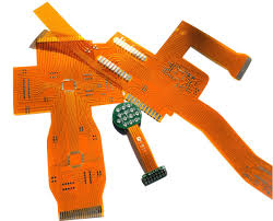
While standard printed circuit boards are made from woven fiberglass impregnated with epoxy resin, flex circuits use a different substrate material. The majority of flex circuits have a polyimide base, which is very flexible, tough, and heat resistant. This allows the flex circuit to withstand repeated solder reflow cycles, thermal expansion and contraction, and other manufacturing processes that would damage rigid boards.
What are the key differences between rigid and flexible PCBs?
During the design phase, the flex circuit layout is designed using PCB software according to the expected mechanical and electrical requirements of the end product. This includes the placement of components, the positioning and routing of traces, and the specification of their lengths. The output files from the design software are then used to create copper layers that are printed on the flex-circuit substrate. The copper layers are then plated using an electroplating process. This step is important because it makes sure that the traces are deposited with proper tolerances and impedance.
It is also recommended to stagger traces rather than stacking them one on top of the other. This can prevent the i-beam effect that is common in rigid PCBs and causes them to crack or break under too much pressure.
Another special consideration when designing a flex circuit is to choose whether or not to include a solid ground. Solid grounds are typically used on rigid PCBs to ensure good conductivity, but they can cause the flex circuit to become stiffer under excessive pressure. It is more practical to use a hatched ground on a flex circuit, as this reduces the overall thickness while maintaining good conductivity and flexibility.
Once the copper layers are plated, the flex circuit is ready for testing and assembly. If the circuit is found to be able to perform its intended functions under normal conditions, it can then be released for production. PCBWay may add a metal house to specific areas of the flex circuit, in order to increase its mechanical strength and protect it from electromagnetic interference (EMI). This option will increase the cost. In addition, if the circuit is to be tested for compliance with standards, this can also increase the price significantly.